Bandsaw Blade Tension Gauge
Changing blades on a bandsaw or large sawmill requires properly setting the tension of the new blade. If you run a sawmill these gauges (tensiometer being the $20 word for it) are part of the required tools of the trade. Unfortunately they cost anywhere from 200 USD up to 800 USD.
Sawmill blades require a tension from 17,000 PSI up to 20,000 PSI for a 2-inch wide blade. Woodworking bandsaw blades typically require 15,000 PSI but the wider 3/4-inch blades can go as high as 20,000 PSI. Bimetal blades are even higher, some requiring as much as 30,000 PSI.
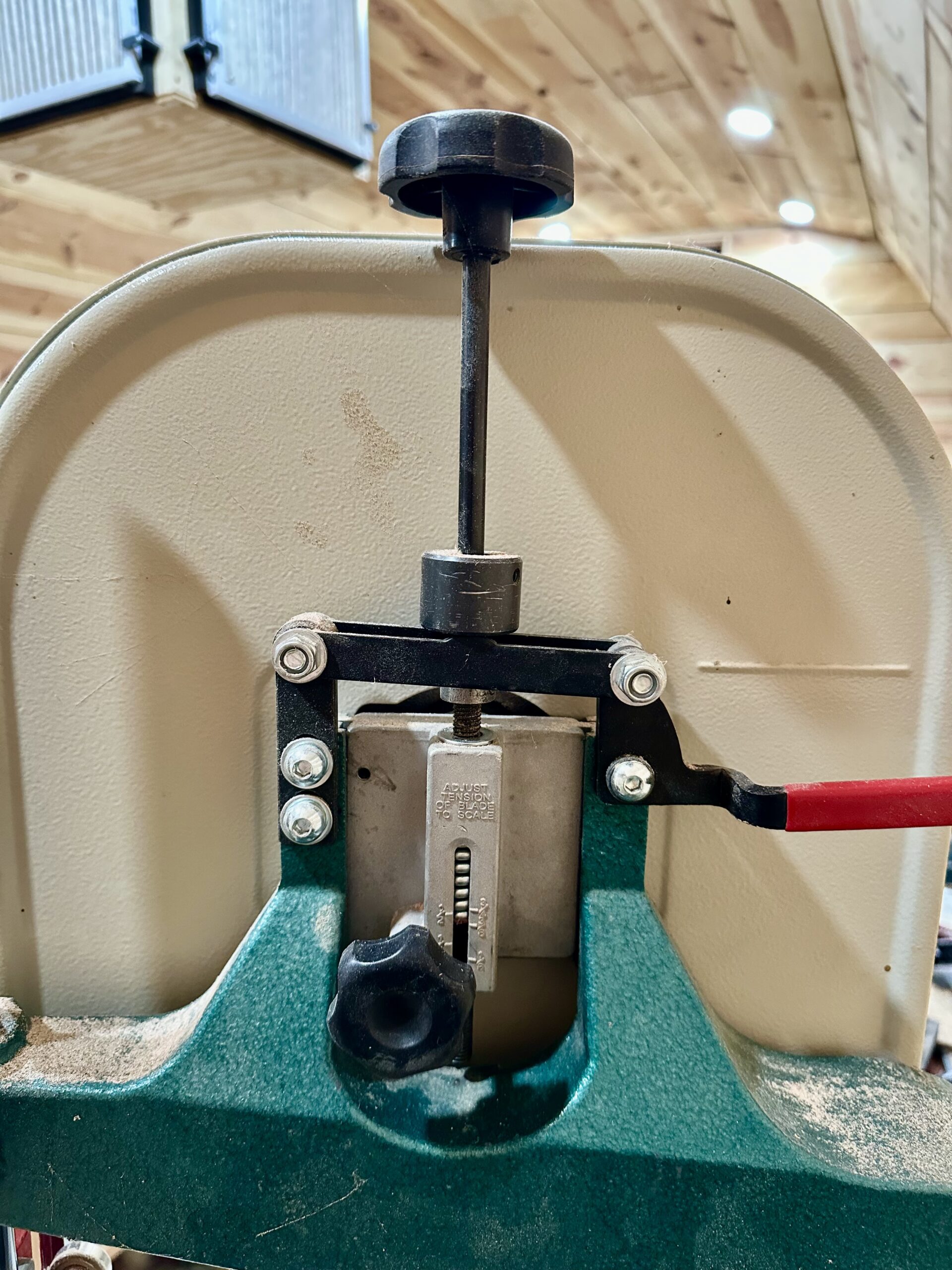
For normal bandsaw users like me there is a gauge of sorts on the back of the saw that tells you when to stop cranking the tensioning knob. It is marked in widths of the blades supported by the machine and does not display the actual tension but the idea is the same. However, as the spring gets old and worn, or the screw shaft starts to wear, adjusting the tension becomes more of a guesswork effort at best, as was the case on my old Grizzly G0555 bandsaw I purchased used.

This is when a gauge comes in handy. The idea is to be able measure the length of a section of the saw blade and then measure how much the blade stretches as tension is applied, in thousandths of an inch. From these two measurements there is a formula that will tell you what the value of the tension is (in PSI). I have put that in an appendix for those interested.
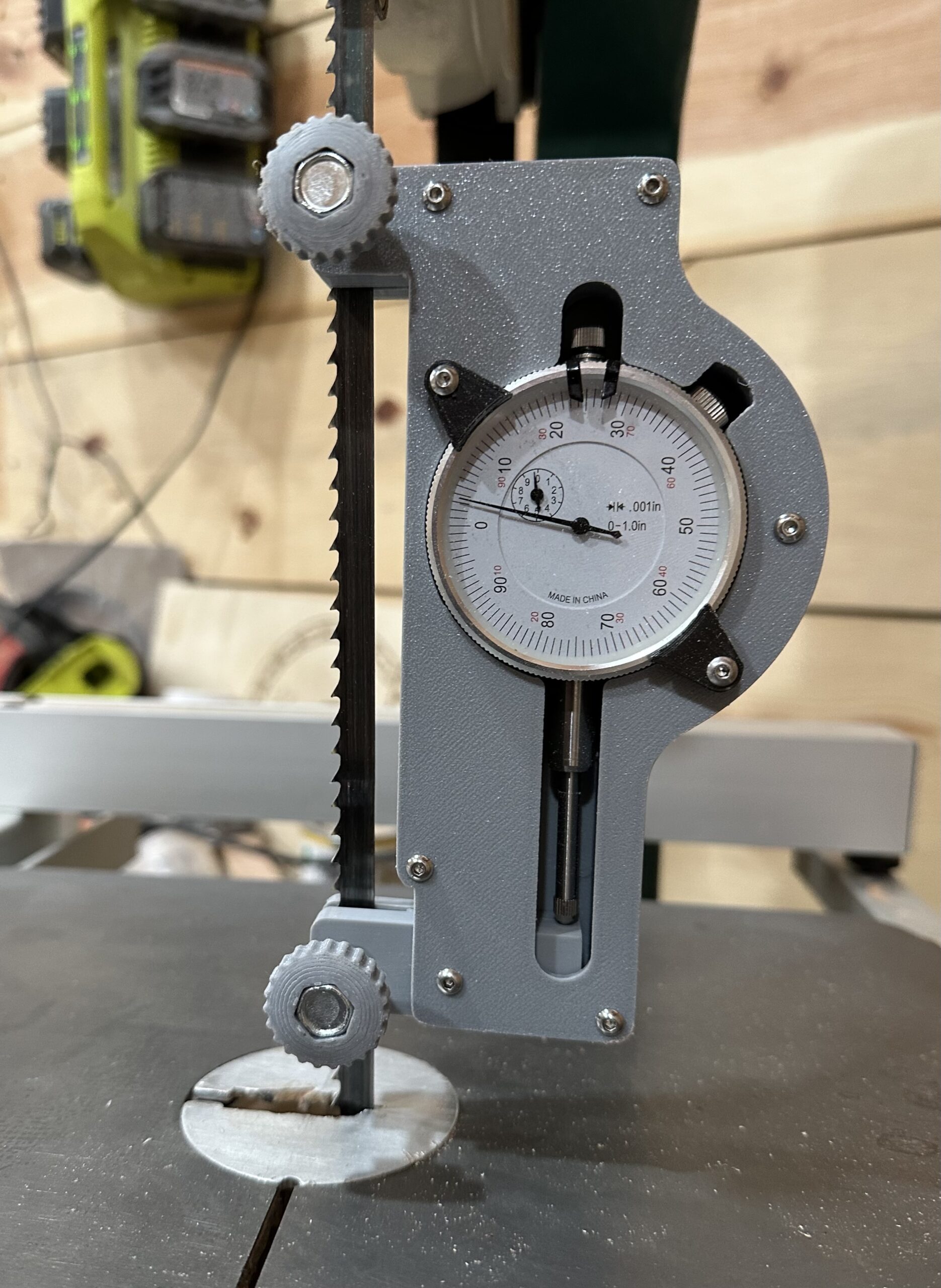
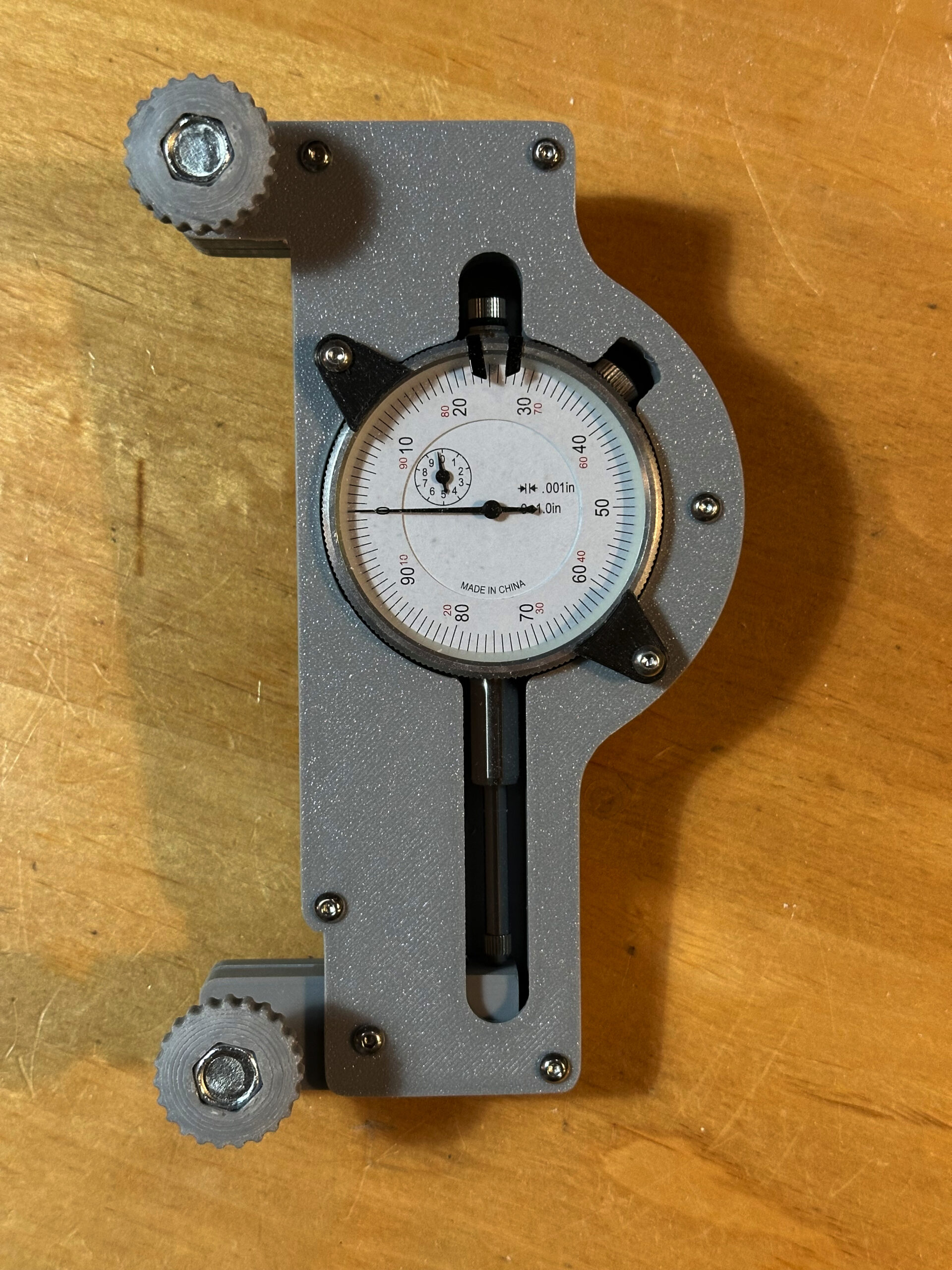
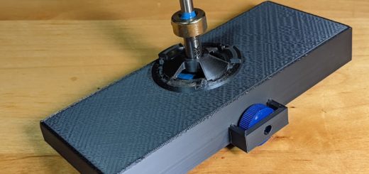
Making a gauge from an ordinary dial gauge is straight forward and there are many DIY versions one can find on YouTube and elsewhere. I decided to make one that looks more like the high end models. The casing holds the dial gauge firmly in place and when the dial indicator reads zero, the spacing between the two attachment points is 6 inches. Using the formula in the appendix, I know that for every 1 thousandth of an inch, I am adding 5,000 PSI of tension.
Finally, I know this gauge is not absolutely necessary as there are other alternative ways to adjust blade tension. Even if a blade calls for 15,000 PSI it will cut just fine at +/- 1,000 PSI or so. This makes it possible to set the tension by simply measuring the deflection of the blade at rest when tension has been applied. A 1/4-inch deflection is a good rule of thumb. There is also a technique known as the flutter method which works reasonably well. Lastly, there is a product known as the EZtension tool that will accurately set your tension to 15,000 PSI very quickly and costs around 40 USD. The tool is limited to this tension value and does not work for other blades.
Making the Gauge
All of the files to 3D print your own parts for this gauge can be found at Printables.com. The dial gauge it was designed for is a Pittsburg branded unit sold through Harbor Freight stores here in the USA. If you need to adapt this to a different gauge, send me a message and I will send you the FreeCAD files I used for this design.
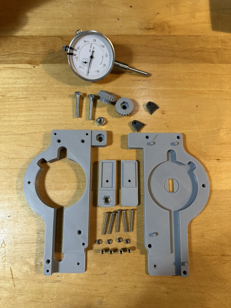
Aside from a 3D printer and some CA glue, you will need the following hardware.
- Dial indicator gauge, Pittsburg branded unit from Harbor Freight
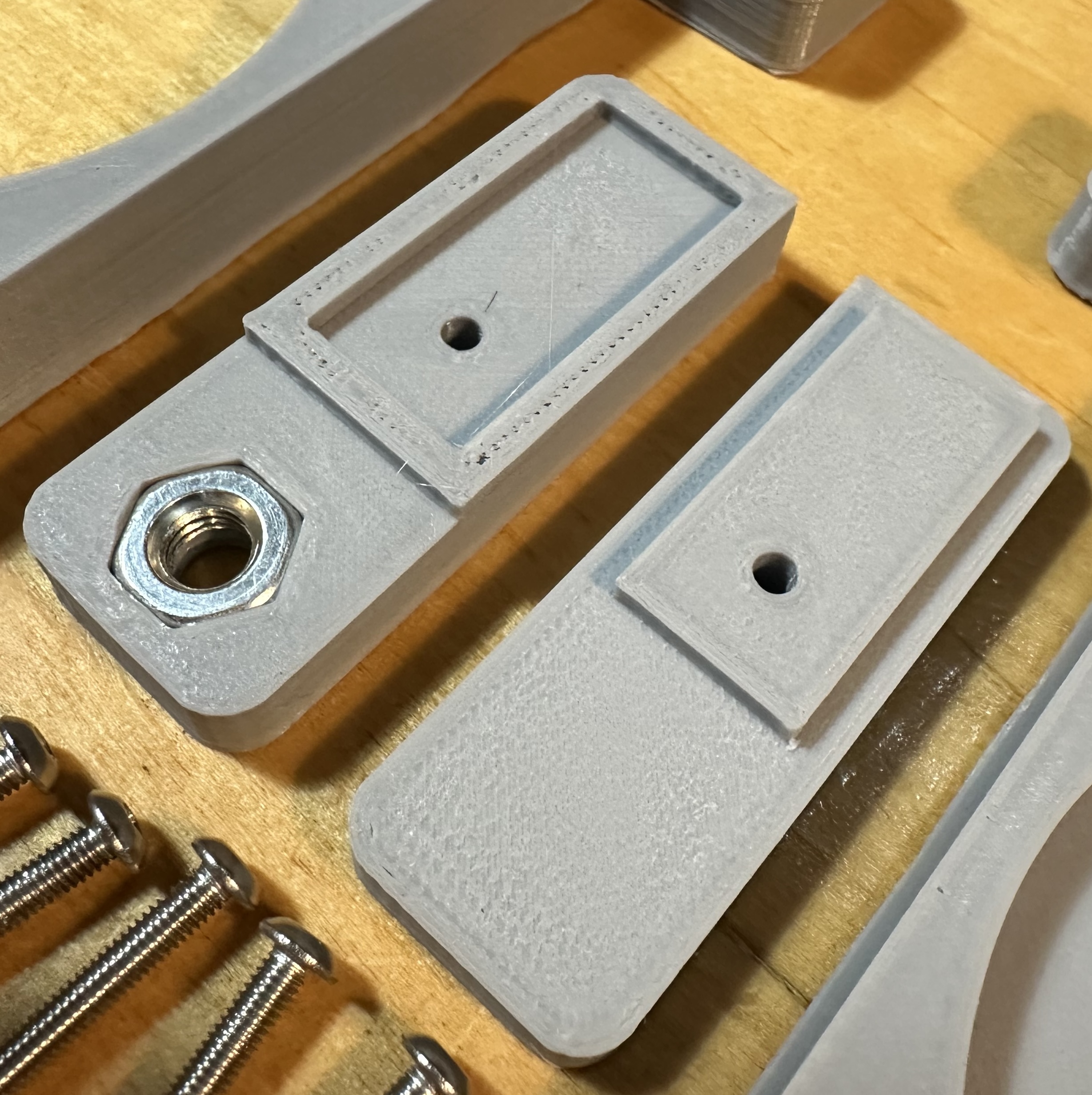
- (2) 1/4-20 x 1-3/4” bolts
- (2) 1/4-20 hex nuts
- (5) M3x16 cap head screws
- (2) M3x10 cap head screws
- (1) M3x25 cap head screw
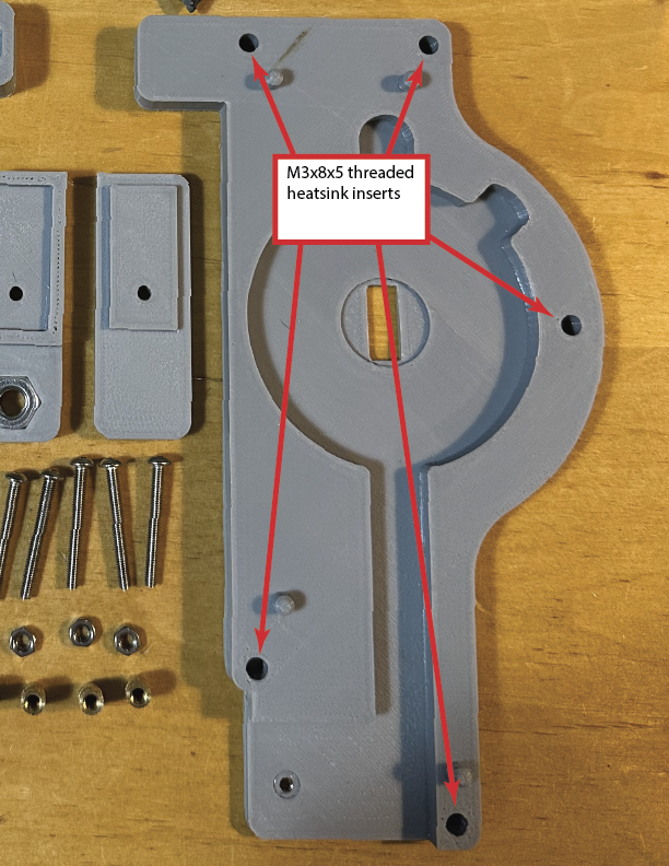
- (5) M3x8x5 threaded heat inserts for plastic
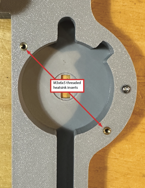
- (2) M3x6x5 threaded heat inserts for plastic
- (1) M3 hex nut
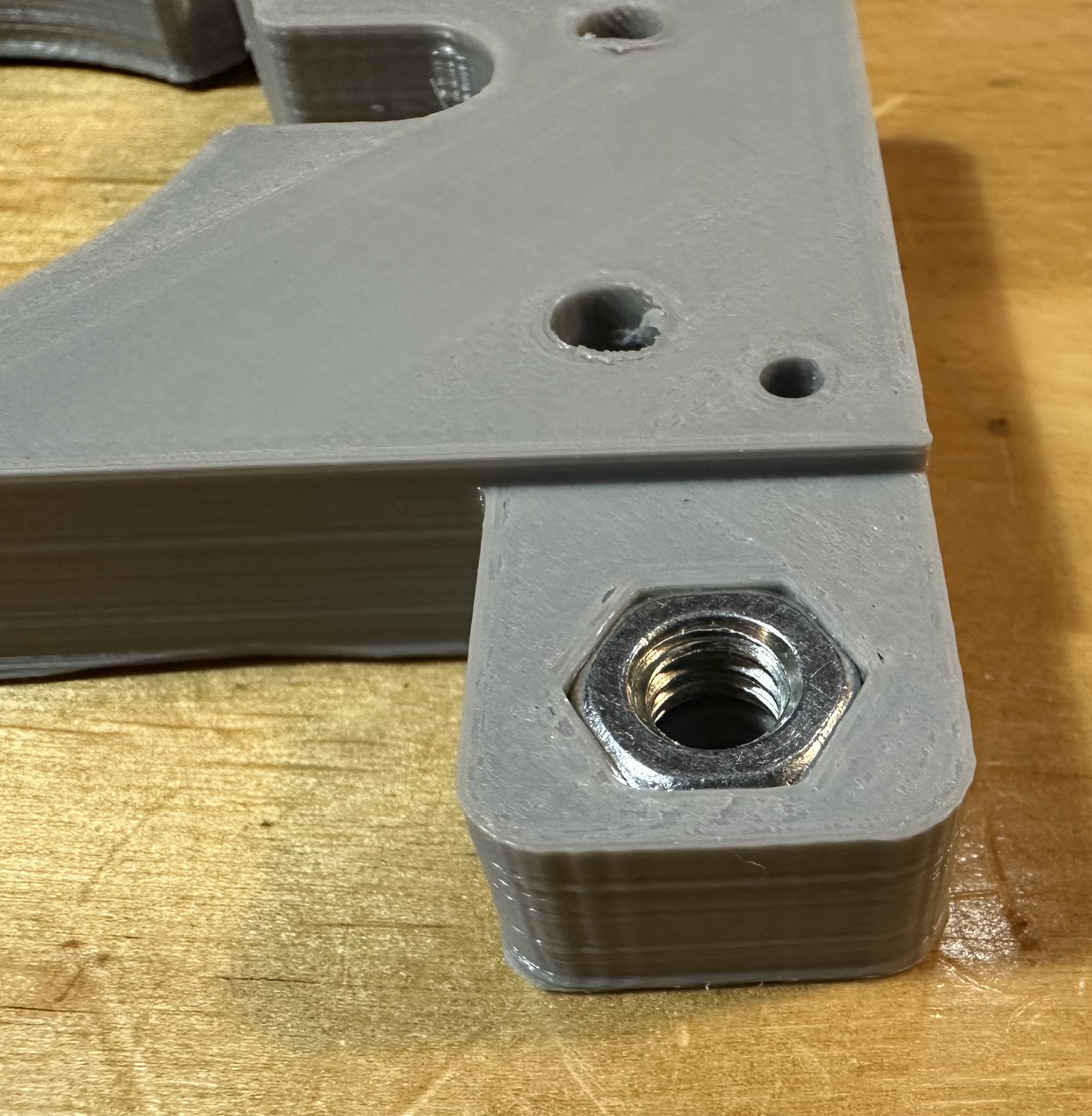
The case for the gauge is printed in two halves that bolt together. This is done in order to make it possible to slip one of the 1/4-20 hex nuts into position before assembly. The same goes for the lever that clamps to the lower portion of the saw blade and which interacts with the gauge probe.
I printed my components in PETG but there is no reason PLA or some other filament would not be suitable. There is no stress applied to the gauge at all. The parts all print without the use of supports. The upper case section is flipped over on the print bed. The upper part of the moving lever is also flipped over on the print bed.
After the parts have been printed and cleaned up, you will need to install seven threaded heat inserts into the spots shown in the photos. The five M3x8x5 inserts are for bolting the case together and the two M3x6x5 inserts are for securing the hold down clamps to keep the gauge from falling out. The M3 hex nut is pressed into place on the back side of the lower case part.
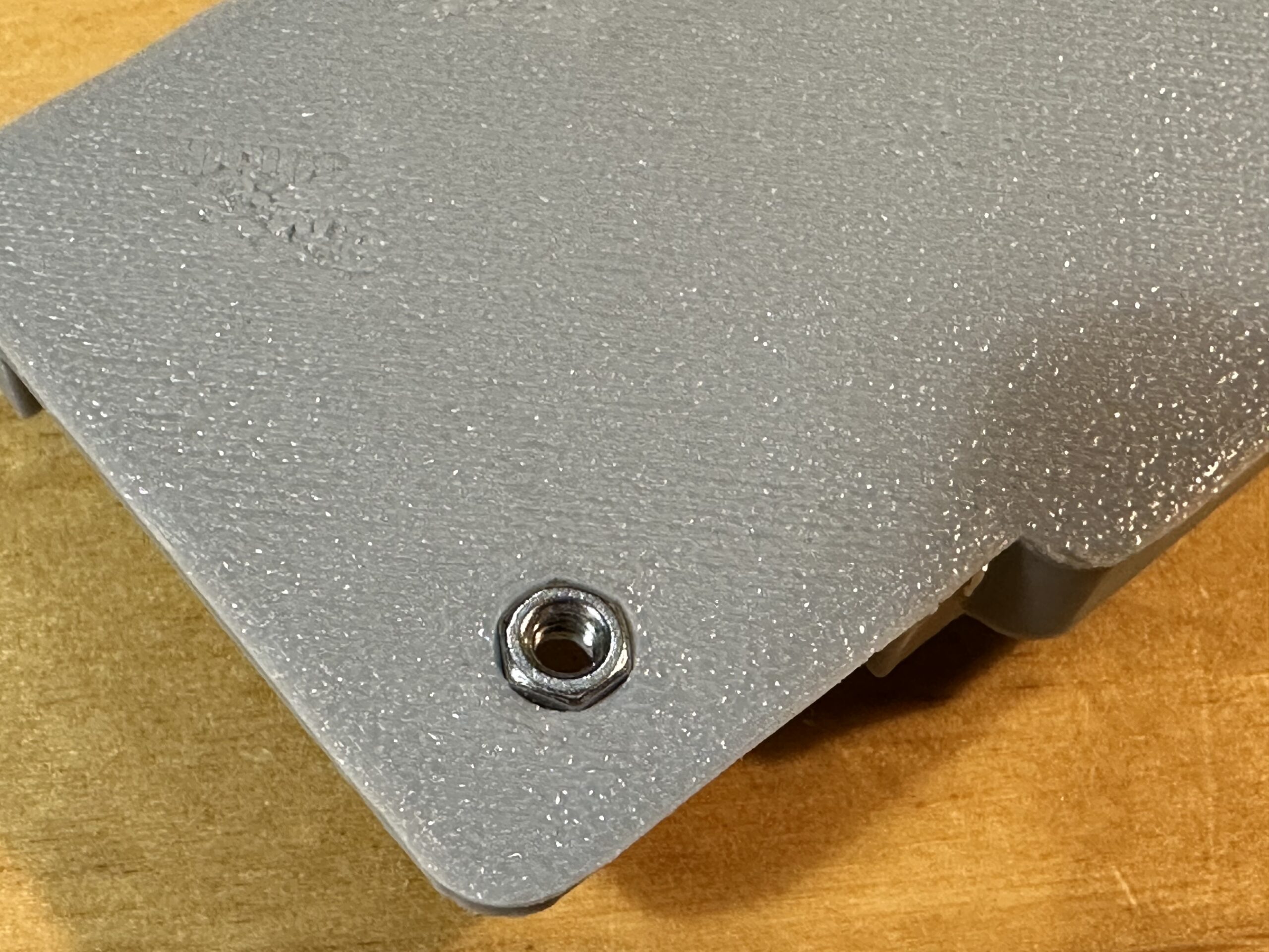
Before bolting the two halves together, press one of the 1/4-20 bolts into place on the upper case body
The two halves of the case body should snap together with the guide pins showing the proper alignment. Then just screw in the five M3 screws to secure it permanently.
Insert the other 1/4-20 nut into the upper lever body. Then apply CA glue to the ridged edges on the upper body and snap the two halves together. Clamp the pieces together until the glue fully cures.
The lever body is bolted to the main case using the M3x25 screw. Make sure that the 1/4-20 bolt hole is facing up, to match the one on the top of the case. Push the screw through the upper case, through the lever, and screw it into the M3 nut you pressed into place previously. This should be snug but not tight. The lever should slide freely on the M3 screw and pivot freely as well.
Slip the dial gauge into the case and use the two M3x10 screws and the hold down clamps to keep it in place.
Finally, press-fit the two 1/4-20 x 1-3/4-inch bolts into the printed knobs. Then screw the bolts into the 1/4-20 nuts. These two bolts are tightened against the saw blade when tension measurements are made.

Using the Gauge
Slip the gauge onto the bandsaw blade when there is no applied tension. Use the two knobs to clamp the gauge in place. Depending on the dimensional accuracy of your 3D printer, the clamping points should be 6-inches apart and the bottom of the dial gauge should be pressed against the lever. Measure this distance and write it down. This is the length L in the formula given in the appendix. To make reading the gauge easier, rotate the indicator so that the zero-point lines up with the needle in this position.

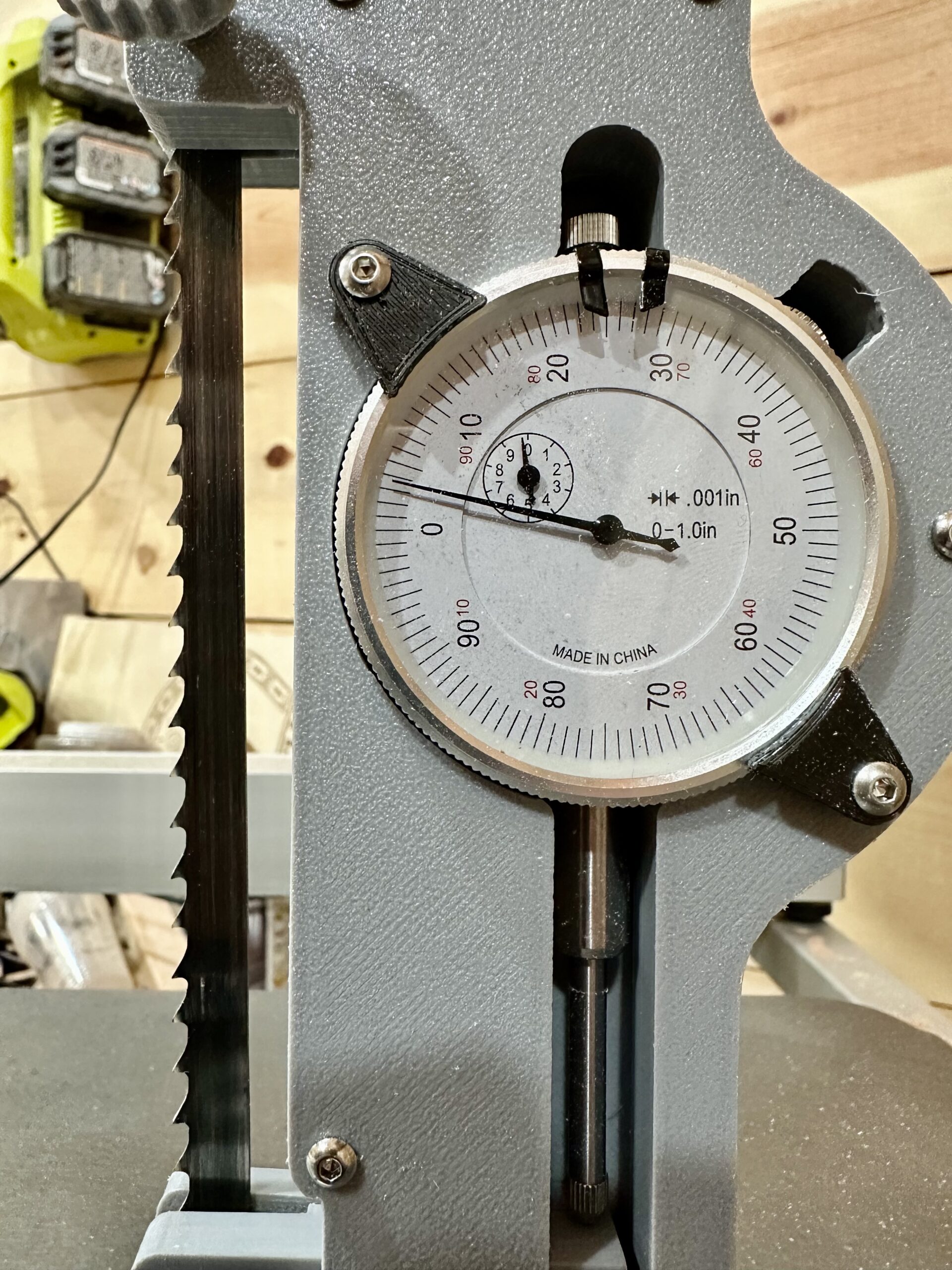
Start applying tension to the blade as you normally would. As it starts to increase you should see the dial indicator start to move. There is roughly an increase of 5,000 PSI for every 1/1,000th of an inch measured. My blade called for 15,000 PSI and I stopped just a bit over that.
Appendix
The physics behind how this gauge works is based on the mechanical properties of solid materials to stretch or compress when tension is applied. The stiffness of a material is determined by a property known as Young’s modulus for stresses that do not cause permanent deformation of the material.
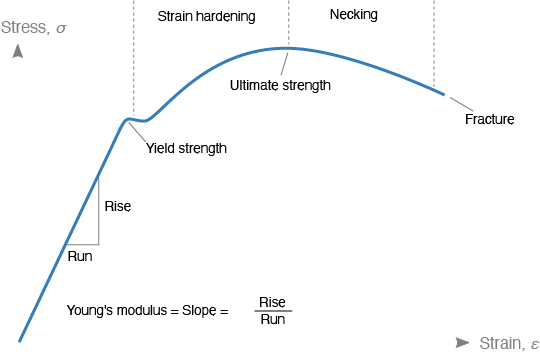
The graph above shows how a material behaves when stress is applied. There is a linear section where the material will stretch in direct proportion to the amount of stress applied. This is the regime in which we tension our saw blades (otherwise they break). The value of the rise over run is the Young’s modulus and it is unique to every material. Tool steel has a Young’s modulus of 29 million PSI. The rise is the applied stress (𝜹), the PSI we exert using the tensioning screw of the bandsaw. The strain is defined as the amount the material stretches divided by the original length of the material,
strain = 𝜟L/L,
where 𝜟L is the change in length and L is the original length.
For the tension gauge, the original length is the amount clamped between the two bolts before tension is applied. The stretched amount is the value shown in the dial gauge.
With these parameters, we can calculate just how much we need to stretch the saw blade in order to achieve a certain tension. For example, suppose we need to tension for 15,000 PSI. We have
Y = stress/strain = 𝜹 / (𝜟L/L) = 𝜹⋅L / 𝜟L
We can be rewrite this for 𝜟L,
𝜟L = 𝜹⋅L / Y.
Using 𝜹 = 15,000 PSI, L = 6 inches, and Y = 29,000,000 PSI we get 𝜟L = 0.00310345 inches, rounded to 0.003 inches.
Thus we know that when the gauge reads 3 thousandths of an inch, we have achieved 15,000 PSI. Note that this also means that for every 1/1,000th of an inch we have added 5,000 PSI. This will allow you to set the tension for any blade in the future.
Recent Comments